Toner Transfer Method
Toner transfer as the name suggest involves transfer of ink (toner) from one surface to other. In this case it involves transfer of ink from the photo paper to the copper clad.
Toner transfer method comprises of :
Printing of layout
Copper Clad Cutting
Sanding
Pressing
Removal of paper & Needling
Etching
Scrubbing
Conformal Coating
Grinding & Filling
Drilling
Soldering
The steps for single side board fabrication using toner transfer method are explained below :-
1. Printing of layout
Toner transfer involves transfer of ink (toner) from one surface to other. In this case it involves transfer of ink from the photo paper to the copper clad. Printing of the layout(mirrored) is done using a laser printer, on a photo paper of 180 gsm.
2. Copper Clad Cutting
Before starting the process, we need to have the copper clad cut in the desired shape. We can cut clad using two methods:
Using Hacksaw : This is a manual method of cutting the copper clad in which the bigger copper sheet is aligned at an appropriate position with the help of supports and then is cut using a hacksaw. This method suffers from few limitations i.e. we can cut only limited geometrical shapes such as rectangular(non-curved), etc .
Using CNC machine : CNC is a Computer Numeric Control machine. It executes pre-programmed sequences of machine control commands. Any required shape of PCB can be designed in software associated with the CNC machine. The CNC machine then cuts accordingly. Example of such a CNC machine is ShopBot(photo of shopbot machine cutting a PCB. In the photo tabs will also be highlighted + photo of partswork file to demonstrate how I thi looks.)
After Cutting copper clad, generally the edges are not smooth and uniform and if tabs have been added while cutting using shopbot, then boards need to be filed. A file is a hand tool used to remove fine amounts of material from the cut copper clad. Filled and smooth boards look good.(photo before ,during and after filling)
3. Sanding
The copper clad board used for fabricating PCBs forms an oxide layer on its surface when exposed to air (since copper is a reactive metal) which in turn reduces its conductivity. Hence, this oxide layer needs to be removed with the help of sanding. It is carried out using a sandpaper (grit no. 120). Size of the sanding paper will be based upon copper clad size. In this process, sandpaper is rubbed over the copper clad board along one direction to make it a smooth surface. (we won’t be able to etch the board).
Precautions :
The sandpaper should be rubbed only along one direction otherwise an uneven surface will be created at the microscopic level which in turn will block the complete transfer of the ink.
Sanding should not be done for a very long time as copper starts vanishing.
One shouldn’t hold the sanded copper clad with bare fingers as our skin contains different types of impurities which can contaminate the exposed copper. Thus, we should always hold a sanded copper clad with a tissue paper.
After sanding is complete, we get a shiny bright surface with horizontal/vertical lines.
(photo of cut copper clad,sand paper,sanding process,copper clad after sanding)
4. Pressing
This step justifies the meaning of the method’s name:”toner transfer method” as in this step we transfer the imprint of the circuit tracks onto the copper board using a press. With application of appropriate and uniform heat and pressure the ink transfer will be complete in 2-4 minutes.
Steps :
i. Adjust the Iron Press settings to Wool (around 150°C).
ii. Keep the printed layout (facing toward the clad) on the copper clad, align the print as per the copper clad. Now put the iron press on about half of the surface of printed layout while holding the layout with the other hand. Keep the iron press in same position(while applying pressure) without any movement for about 20 second. Now lift the iron press and redo the process for remaining area. It can be observed that paper will start sticking on the copper clad. Now move the press in uniform motion on the total area, apply uniform pressure. The total time for this process should be around 2 minutes for a board upto 15cm X 15cm. For bigger boards time should be increased.
iii. To hold the edges of board while in between the process, use tissue paper (as the copper clad will be hot).
iii. There should be an insulator between bench and PCB such as cardboard to protect bench from heating.
iv. Overheating must be avoided during pressing. Due to overheating colour of copper clad changes to reddish. Overheated board is not preferred, chances of copper tracks removal increases during etching and soldering work.
v. Bubbles should be strictly avoided to ensure that the ink is completely transferred from photo-paper to PCB. To avoid bubbles, start pressing from one edge and press for 10-15 sec and then move progressively to opposite edge (pressing each time for 10-15 sec). Then press uniformly on PCB.
AFTER REMARK:
There is no visible proof that the ink has been transferred but if one takes care of above points while ironing, there is a minimal scope of failure.
Starting gesture for pressing:
During pressing:
After Pressing:
5. Removal of paper & Needling
After pressing, the board is allowed to cool for a minute, then it is put into a tub of water where the paper is removed from its surface by manually rubbing it gently, thereby exposing the ink tracks. Slowly and slowly the whole paper will peel off, leaving the toner on the board. The paper should not be removed directly in one go otherwise the toner will not get transferred on our PCB. Avoid using nails or other tools for this process.
Setup before starting the process:
During paper removal:
After Paper Removal:
After removal of paper, wait for PCB to dry. With the help of a fine dissecting needle, remove all the extra paper left other than tracks like paper between parallel tracks, holes, etc. After this, ensure that all the tracks are retained.toner. If there are only one or two errors then draw those tracks with a permanent marker (overwrite at least 4-5 times) before continuing to etching. If there are more errors, it is recommended to do the above processes again. In case of any shorting, use a pointed object (eg-dissecting needle) to remove it.
In case if you want to add any text, then you can write it on clad using a permanent marker or it can be done in the layout designing software only.
6. Etching :
Etching in this context is the process by which ferric chloride reacts with copper and displaces it. After this process, all the exposed copper is removed and we are left with a substrate board and only the tracks of the required layout. The ink acts as a shield for the copper beneath and once this ink is removed by scrubbing rigorously, the copper beneath it is exposed, thereby forming conducting tracks.
i. Preparing the etching Solution:
The solution for etching is prepared by mixing FeCl3 crystals and distilled water(for better reactions) or normal water in a plastic bucket. Proportion is 150g of FeCl3 crystal in 1000 mL of water. During winters hot water can also be used, so that the process becomes fast or perform the process in sunlight so that the heat helps in etching. Mixing should be done carefully, as the reaction is exothermic.
A proper plastic container should be chosen so that it is comfortable to place the board and etch. Do not use this container for any other purpose than etching.
ii.Etching Process:
Make sure that the tracks developed using toner transfer method are perfect before starting etching.
Take the bucket containing etching solution and place the board to be etched carefully.The copper parts which are directly in contact with the chemical will corrode/etch. Periodically shake the container for making the process fast.
The etching time differs depending on the board size, chemical concentrations, etc. Usually it takes around 10 minutes.
Regularly check the board whether it is etched or not.Generally etching starts from corners.Wait until the board gets etched completely.
While shaking the bucket, make sure that the tracks on the board are not disturbed.
After etching inspect the board carefully if it is properly etched. Make sure it does not have islands of copper left over it. If so, drop it in the solution and etch it clean.
Once, etching is complete take the board out of solution (wear gloves). Hold the board with help of tissue paper. Rinse the board with water so that the solution is removed from the board.
Setup: Bucket containing the solution with gloves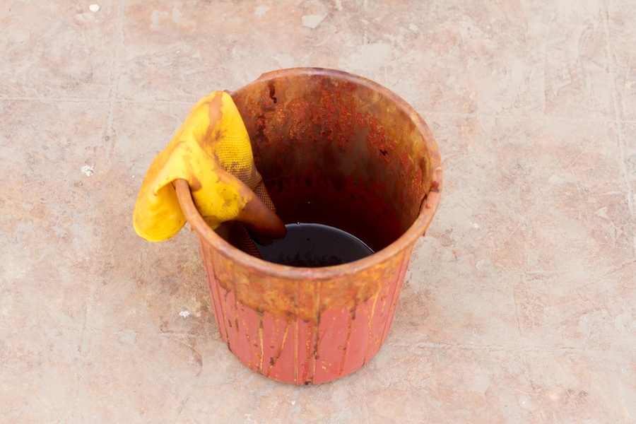
Before Etching : Unecthed board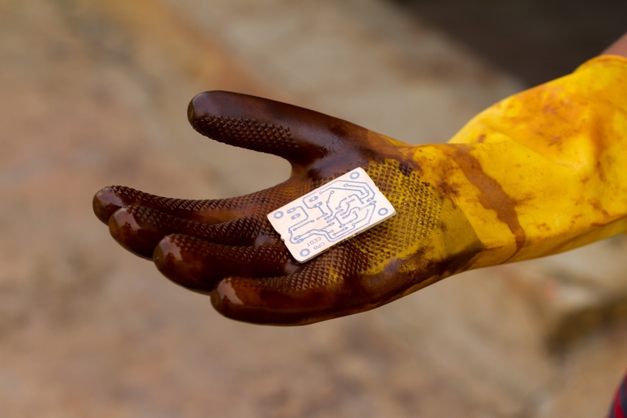
During Etching : Movement of the solution to speed up the etching process 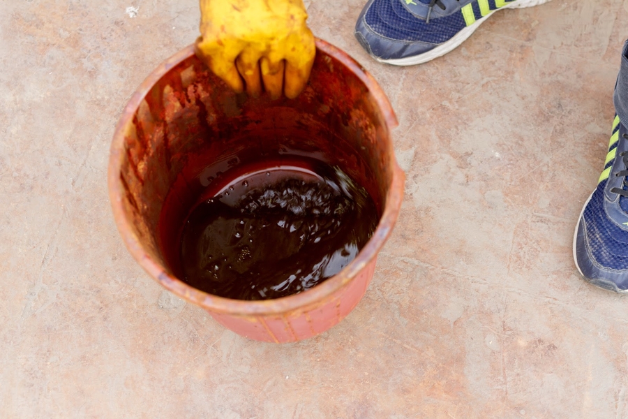
After Etching : Exposed copper etched away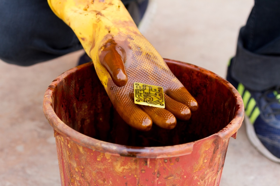
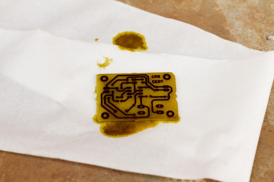
Precautions:
Ferric Chloride is toxic. It can cause burning or irritation. Proper safety precautions need to be taken. Do not let the etching solution fall on clothes or footwear, decolurisation of fabric will take place in such cases.
Use of hand gloves is must during the whole process i.e. do not touch FeCl3 with bare hands. Also, check the condition of gloves prior to handling of solution.
Do not use any metal utensils or metals during the mixing process(Use glass or plastic trays).
While etching, cover your nose and mouth, the fumes may affect you. Wear eye protection equipment. Be attentive while handling etching solution.
After Etching one time, Fecl3 can be reused for next time, but for this purpose store it in cool place away from sunlight.
If the etching solution is not reused, it needs to be disposed of. Baking soda will produce a chemical reaction with ferric chloride that will render the solution relatively harmless to the environment. This is process should be done in most careful manner. One could also reach the hazardous waste collection facility in locality. Disposing methods are available from different sources, please take care of the waste treatment policy of your country.
7. Scrubbing
This process removes the ink from the PCB and exposes the pure copper beneath it. It is done with the help of scrub and a dishwashing liquid (eg - dettol, Vim etc).
Additional Info: Instead of a scrub, sandpaper can be used as well which will fasten this process but it is avoided usually because if not done in one direction, it can remove the copper track.
Before Scrubbing: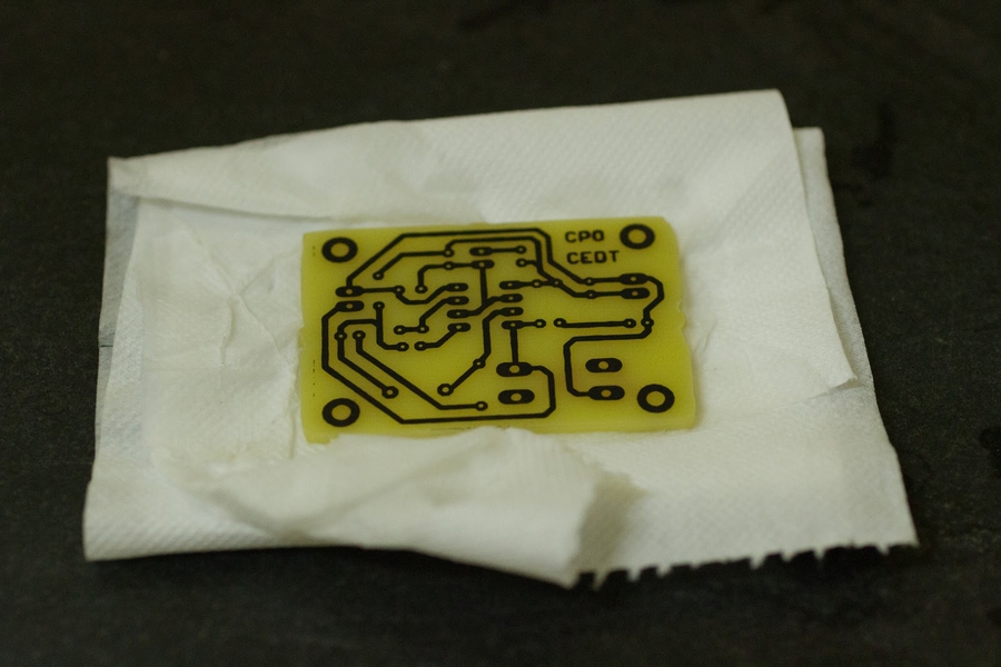
During Scrubbing: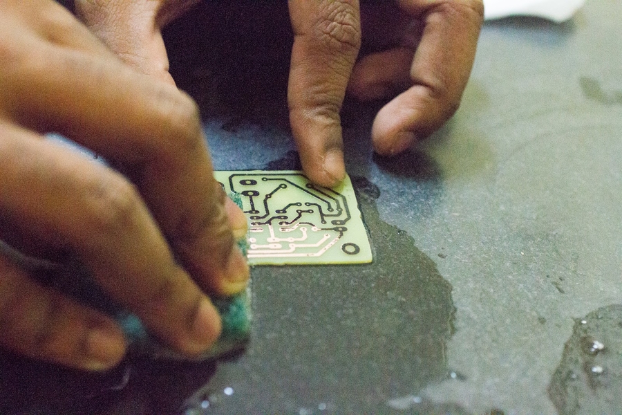
After Scrubbing: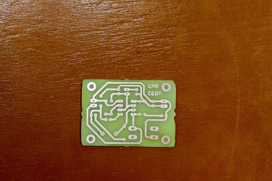
Conformal Coating :
After scrubbing, the copper on the tracks gets exposed and hence the formation of copper oxide layer will take place which will hinder the electrical conductivity of copper.
DC Acryform is a fast drying, single component conformal coating for application on printed circuit assemblies. Having very good solderability and excellent flexibility. DC Acryform protects the PCB from humidity, fungus, and corrosion. It is easy to apply, has a long shelf life (2 yrs) and is easy to remove. It is transparent, coated components are easily identified. Single components may be replaced by soldering or desoldering directly through the coating.
DIRECTIONS:
Clean surface thoroughly.
Shake aerosol well. Repeat while using.
Keep PCB horizontal when spraying.
Spray from a distance of 20-25 cm in light even coats.Best results obtained with two thin layers than one heavier layer.
If clogging occurs remove button and clean with a fine wire.
PRECAUTIONS:
Avoid contact with skin or eyes. ln case of contact, wash affected areas with soap and plenty of water. Seek medical help in case of prolonged symptoms.
Avoid inhalation, use the product in a well-ventilated area with exhaust fan. Use of mask is recommended.
Do not spray onto a naked flame or incandescent material.
In case of excessive spray (copper clad gets whitish), remove it by applying alcohol (methylene chloride) using a brush.
(photo while doing spray)
9. Grinding and Filing
It is done to remove extra area from the PCB and for better finishing. In some cases, it is also done to obtain a specific shape/size of a PCB.
10. Drilling
To insert through hole components we need to drill holes on our PCB. This is done using a drilling machine. Different drill bits(in general,carbide bits) are available depending on the diameter of the hole (eg - 0.7mm, 0.9 mm, 1.2 mm, 1.5 mm). Usually, the supporting screws are 3mm ones, height may depend upon user (generally it is 10mm). They are to provide ‘legs’ in other words, support to our PCB and prevent pcb to make direct connection with table.
In our case we will be using Dremel Model 3000 with workstation 220. In this model, there are switch setting indicators marked with a line. Slide to the number on housing to select the operating speed needed.
The settings for approximate rpm are:
Switch Settings
Speed Range (rpm)
2
5,000 - 8,000
4
9,000 - 15,000
6
16,000 - 21,000
8
22,000 - 27,000
10
28,000 - 32,000
Introduction and Setting up of dremel tool: The Dremel multitool is a handheld rotary tool that uses a variety of attachments and accessories.
Note*:It is advisable to read the owner's manual that comes with the dremel tool before using it for the first time.
To insert a bit: Place the bit into the hole at the end of the Dremel and back it out slightly. Tighten the collet nut so that the bit is held tightly and doesn't move.
To remove the bit: Press down on the shaft lock button while turning the collet. This should loosen the bit so you can replace it.
Procedure for drilling:
Appropriately place the board to be drilled on the base , i.e. there should be proper alignment of the board and the drilling bit.
Set the speed of the dremel tool at 4(the speed range is 9,000 - 15,000).
Hold the handle with one hand and the board with the other.
Switch on the machine and slowly bring the bit close to the board (as there are chances of breaking up of the drill bit) by moving the handle.
Pierce the board at the desired place and when the task is done, uplift the bit back to the normal position.
Clean the drilled area by blowing air and make sure that the hole is done perfectly.
Precautions to be taken care of while setting the dremel tool and then drilling:
Wear eye protection while using Dremel.
Make sure to insert and change the bit when the Dremel is turned off and unplugged.
Clean your Dremel after each use. Keeping your Dremel clean extends the life of the tool.
After you are done, remove the bit and place the bits back in the case.
Keep your workspace clean.
Drilling machine: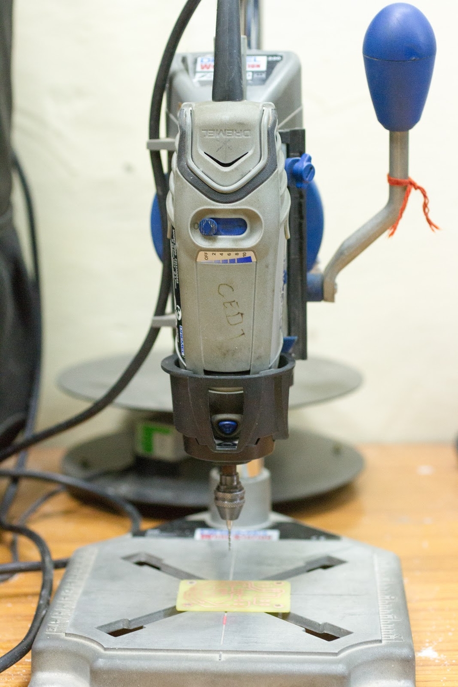
Initial Setup: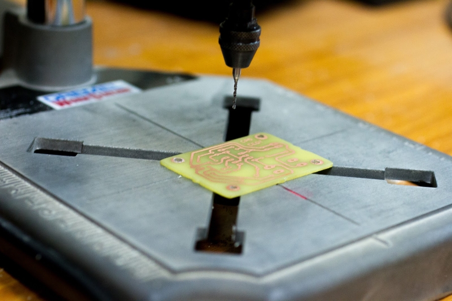
During Drilling: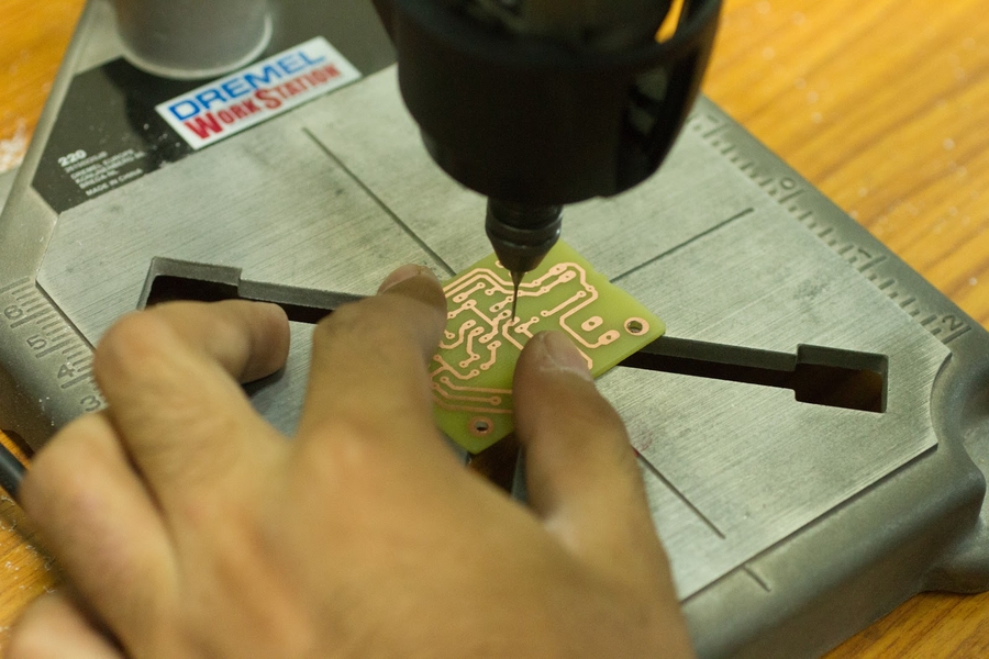
11. Soldering:
This is the final step of PCB fabrication, i.e fixing the components on the board. Before starting soldering, assemble tweezers, wire cutter, solder wire, jumper wire, soldering station or solder iron, all components according to BOM. With soldering station, we can set the temperature of soldering iron as per requirement. We will set 325°C for our purposes as it is the optimum temperature for solder wire to melt and joints are soldered properly. The soldering station should be kept on our “work hand” side (right side for people who are right-handed and left side for people who are left-handed) so that we don’t have any problem while soldering. Soldering iron stand should be kept on left side of soldering station for right-handed people(as shown in picture) and on right side of soldering station for left handed people this will prevent the wire of solder rod from coming in contact with solder rod. Keep the printout of Board layout and BOM on normal paper handy so that position and value of a given component is easily determined.
Tools being used here are:
Tweezers - Very fine tip, straight type
Wire cutter - Multitec 06 Micro shear
Soldering station - Weller WSD71,
Soldering tip - Chisel type
Solder wire - 24 Gauge (60/40 type)
Jumper wire - 26 Gauge
ARRANGEMENT: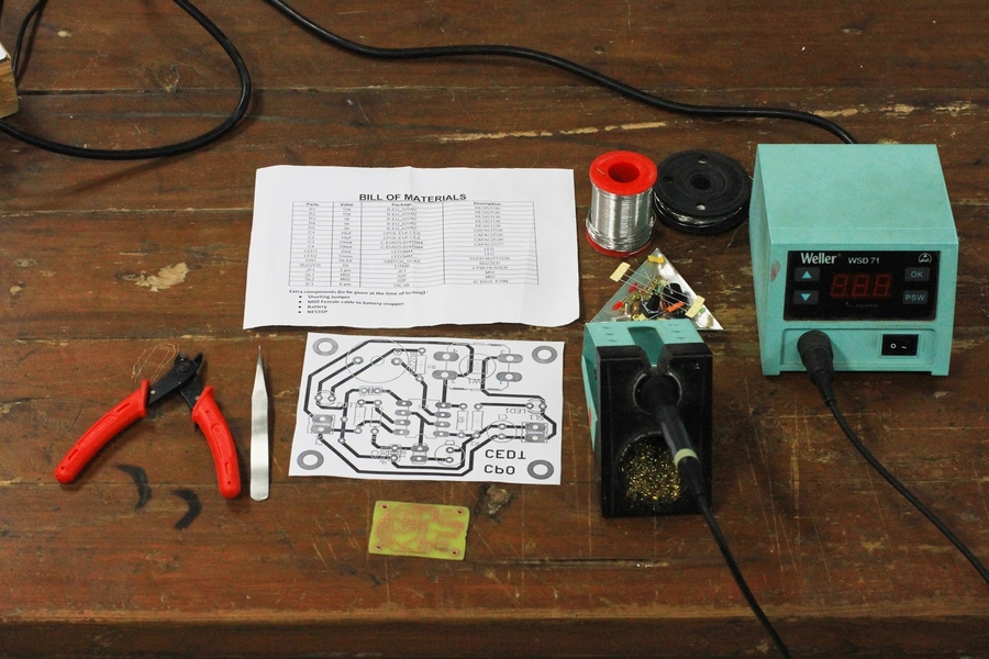
Make sure that the soldering iron tip is clean. For cleaning, you can use a wet sponge.
→Tips: Solder components heightwise. Eg- jumpers, smds components, resistors, diodes, ceramic capacitors, leds, transistors, ic base, headers etc. _Pro tip : Keep tolerance band of resistors on one side, the soldered board will look more professional. _Repeatedly clean the soldering iron using a wet sponge. The soldering tip should be covered with optimum layer of solder to prevent corrosion of soldering tip.
→How to solder resistor:
Choose the correct value of the resistor (calculating it using the colour coding on it) and look at the board layout and identify where it has to be placed.
For the resistor, cut its ends using wire cutter (leads should be of sufficient length). Do not pull the resistor leads.
Put the resistor on the board between the holes. The resistor should be in between the two holes (so distance is equal from both holes).
Using tweezers fold the leads of resistors from where the leads have to go into holes.
Now put the resistor leads into the two holes with resistor being on the top layer. Fold the two leads on the bottom side in case the resistor slips. The resistor should be flat on the board (not in the air).
Now, straighten one wire of resistor/jumper. Bring soldering iron on the pad to heat it. Then bring solder wire on the pad. Solder wire will melt and due to strong affinity of solder with copper, it will form a connection between the copper pad and the resistor/jumper. The whole copper pad should be filled completely with solder and a conical shape should form so as to ensure that it is fixed firmly.
Check and ensure that the resistor is touching the board and is not in the air. Now, straighten the other lead and repeat the process.
Once the resistor is firmly in place, cut the resistor leads above the solder joint with the wire cutter.
→How to solder jumper:
Jumper is a normal copper wire.
Straighten the jumper wire using tweezers, repeat the process to make straight wires.
Cut a piece of jumper wire of length bigger than the distance between the holes using the wire cutter.
Put the jumper on the place where it is to be soldered.
With the help of tweezer, fold the jumper wire so that it is of length equal to the distance between holes.
Now solder both the pads and then cut the extra wire using wire cutter.
→How to solder smd:
Add a small amount of solder on one copper pad.
Hold the component (eg- smd resistor) with the tweezer. Use tweezers to line up the component with pads on the board. Apply a little pressure with the tweezer, pushing the component down onto the board, into the solder, and then touch the iron on the pre-soldered pad so as to melt it. It does not have to be a good solder joint at this point – just enough to hold the component in place.
The component should be held firmly against the board. You can reheat the pad a few times to get the component pushed all the way and pads lined up (placed correctly).
Solder the pad on the other side (of the smd).This should be a proper solder joint. 5. Bring the soldering iron back to the pre-soldered copper pad and apply a little more(as required) solder to it. This will firmly fix the smd component with the board.
→ Soldering polar components: Polar components can only be placed in one way, if they are soldered in another way then the circuit won’t work. So, before soldering them check their polarity in the board layout and place accordingly.
→ Soldering DIP ICs: For DIP ICs we solder IC base on the board. Place the IC base seeing where the notch should be. First solder one pin of IC base then solder the one exactly opposite to it so that it is fixed. Make sure IC base is not in the air. Solder the rest of pins.
->Desoldering :
Identify the terminals for the component to be desoldered. Thoroughly examine both sides of the board to isolate the specific spots holding each component in place.
Using isopropyl alcohol on a toothbrush, gently clean the terminals of the component to be desoldered. Clean only on the soldered side and not anything on the component side.
Using desoldering wick:
Desoldering wick (also called solder wick) is a braid made from copper wires.
A large braid can burn the board or can take too long to heat up. Choose a braid of the same size or smaller than the solder pad, and slightly wider than the tip of soldering iron.
Add a little flux to the braid.
Old, hard solder can be difficult to melt so add a tiny bit of solder onto the terminal.
Place the end of the braid over the terminal you are desoldering. Let the iron rest on the braid without additional pressure, to avoid pushing the solder pad out of place. The braid is hot to touch so hold the braid by the bobbin which is wound around. Wait a few seconds for the heat to pass through the braid and melt the solder.
The braid will wick (draw off by capillary action) and absorb the melted solder. If the solder isn't melted, too much heat could be dissipating up the braid. Try cutting off the end of the braid and using that instead, holding it in place with the soldering iron.
The colour of braid will change as the flux coating is used up and solder is absorbed.
Spool out more of the braid and continue on to the next terminal. Apply more liquid flux to the braid if needed.
If you want to reuse the component, keep the braid and soldering iron away from the component to avoid heat damage. Once all the solder is removed, give the area about thirty seconds to cool, then remove it.
Using desoldering pump:
A desoldering pump, also called a solder sucker, vacuums up melted solder to separate soldered components from a circuit board.
Press the end of the pump until it clicks into place. This compresses a spring, and latches it in the depressed position.
The heat from the soldering iron can damage sensitive components such as integrated circuits or transistors. To dissipate some of the heat, clip a metal alligator clip between the component and the terminal you plan to desolder.
Switch on soldering station. Using the tip of your soldering iron, heat the old solder until it melts. You can push the terminal with the soldering iron tip at the same time to help free the component as the old solder melts. Use an old soldering iron if you have one, since pushing with the iron can wear the iron down.
Touch the tip of the desoldering pump to the solder pad and melted solder, without applying pressure. Release the spring (usually by pushing a button on the side) and the piston will shoot back quickly. This creates a vacuum which pulls the melted solder up into the pump. The tip of the pump may melt a little during use. Most pumps either have replaceable tips or are cheap to begin with, but you can try to reduce the damage by pausing for a moment after melting the solder. Melted solder can harden again quickly. Work with only one terminal at a time. For the greatest efficiency, hold the soldering iron in one hand and keep the desoldering pump ready in the other.
After each use, push the pump down again over a ‘trash can’ to clear out the solder. If you leave the old solder inside, it can leak back out as you go to vacuum the next terminal.
You may notice brown resin stuck around the solder pad, since this can melt when heated. You can remove this with a commercial resin cleaner, or scrape it away very carefully with a small, flat-head screwdriver or steel wool.
Finish by cleaning the area with a toothbrush dampened with isopropyl alcohol.
Board layers can accidentally get separated during desoldering process. This will ruin the circuit. Hence, the process needs to be done carefully.
Last updated